

How a monostable multivibrator using IC 555 works? – Detailed study
What is a monostable multivibrator?
monostable multivibrator mode of operation of IC 555 consists of only one stable and one unstable state. The stable state can be chosen either high or low by the user.
Generally, the output of the monostable multivibrator is in low (0) state and it remains in low state until the external trigger pulse is applied. When the external trigger pulse is applied the output switches to a high state (1) and after a specific time it comes back to its initial low state.
Before starting to study the working of a monostable multivibrator I like to suggest you read all about the IC 555.
let us discuss the working of a monostable multivibrator with the help of its construction, circuit diagram, waveforms, and all other details.
Construction of Monostable multivibrator
The following circuit diagram shows a monostable multivibrator using IC 555 in which the pin no. 7 (discharge) and pin no. 6 (threshold) are shorted together. A timing capacitor C is connected at the lower arm of short of pin no. 7 and 6. The resistor R is connected at the upper arm to +Vcc.
The pin no. 2 (trigger) is connected to +Vcc through a resistor of 10K and also connected to ground through a push to on switch S. Whenever we required to change the state of monostable multivibrator a trigger pulse is applied. The trigger pulse is applied by connecting pin no. 2 to ground momentarily by using push to on switch S.
A small value capacitor of 0.01µF is connected at pin no. 5 to prevent the upper comparator from noise disturbances.
The power supply or battery is connected between pin no. 8 (+Vcc) and 1 (Ground). The pin no. 4 (Reset) is connected to +Vcc to avoid accidental rest of IC 555. The output of an astable multivibrator is taken between pin no. 3 (output) and ground. A LED is connected at an output to indicate the output voltage level.

Working of Monostable multivibrator using IC 555
When the power supply or battery is switched on the trigger input (pin no.2) of Lower inverting comparator gets connected to +VCC. Therefore the lower comparator having low output voltage and sets the flip flop which produces the output Q = 1 and = 0. The output of monostable multivibrator is now in a low state.
This state of monostable multivibrator is called a stable state. The output Q of the flip flop is connected to the base of a discharge transistor. The base of the discharge transistor is high (Q =1) therefore transistor goes into saturation condition.
The discharge transistor does not provide a path for the charging of an externally connected capacitor. The saturation state of the transistor clamps the capacitor voltage at the ground. Therefore the monostable multivibrator output will remain in this state until the trigger pulse arrives at trigger input (pin no.2) of the lower comparator.
The trigger input (pin no.2) is connected to +Vcc through 10K resistor as well as it is connected to ground using the push to on switch.
When the switch is pressed momentarily the trigger input (pin no.2) gets connected to ground and trigger pulse is applied to the lower comparator. The lower comparator is inverting comparator now its input voltage is less than its reference voltage of 1/3Vcc so it produces a high output voltage. The upper comparator is a noninverting type of comparator now its input voltage is less than its reference voltage of 2/3Vcc so it produces a low output voltage.
The outputs of both comparators are applied to R and S inputs of the flip flop. The inputs of the flip flop are R =1 and S=0, so the flip flop goes into Reset condition and its outputs become Q = 0 and = 1.
The flip flop output is the actual output of the IC 555 and for now, it is high i.e. = 1. The LED connected at the output starts glowing and indicates IC 555 output waveform started it’s on time. The output Q of the flip flop is connected to the base of a discharge transistor.
The base of discharge transistor is low (Q =0) therefore transistor goes into a cut off condition. Therefore the capacitor starts charging exponentially towards the +Vcc voltage through the resistor R as shown in a waveform. This is called a pulse width of a monostable multivibrator and it is given by T= 1.1RC.
Waveforms of Monostable multivibrator
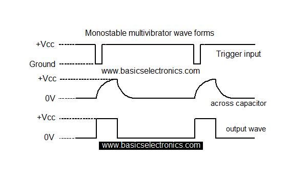
While charging the voltage across the capacitor increases towards +Vcc. When the voltage across the capacitor is slightly greater than +2/3 Vcc the input applied to the upper comparator gets more than the reference voltage of +2/3 Vcc. So, therefore, the upper comparator produces a high output voltage.
The trigger input of the lower comparator is connected to +Vcc so its input voltage gets more than the reference voltage of +1/3 Vcc. Therefore the lower comparator produces a low output voltage. The outputs of both comparators are applied to R and S inputs of the flip flop. The inputs of the flip flop are R =0 and S=1, so the flip flop goes into the Set condition and its outputs become Q = 1 and = 0.
The output of the monostable multivibrator is now in low stable state and t remains in the same state until the new trigger pulse arrives.
Why monostable multivibrator is called a one-shot multivibrator?
as we know the output of the monostable multivibrator is in low (0) state and it remains in low state until the external trigger pulse is applied. When the external trigger pulse is applied the output switches to a high state (1) and after a specific time it comes back to its initial low state. The monostable multivibrator output remains in one state so it is called a one-shot multivibrator.
I hope you understood the working of a monostable multivibrator using IC 555.
you may also need to study about an astable multivibrator using IC 555
you can also read from other authors here.


